An injection pressure regulator (IPR) is a device used to control and regulate the pressure of fuel or liquid in the injection system.
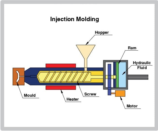
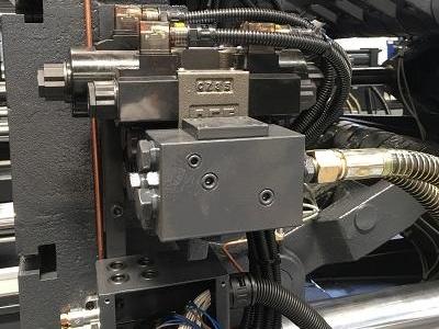
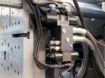
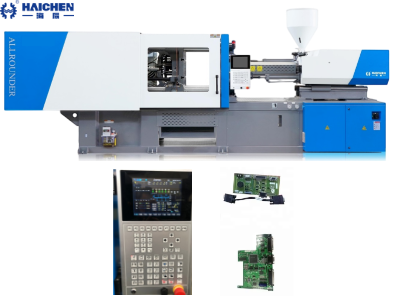
The pressure regulator of the injection molding machine is a highly integrated component of the hydraulic and electronic control systems. The core structure includes hydraulic control valves (such as proportional valves, servo valves), sensors and electronic control units. Its essence is to achieve multi-level precise control of process pressures such as injection and pressure holding by adjusting the pressure and flow of the hydraulic oil circuit to ensure molding quality. The specific implementation method varies depending on the type of machine (hydraulic/electric), but the core goal is fast response and stable control.
The core of the injection pressure regulator is to dynamically adjust the flow rate to stabilize the outlet pressure through force balance. The specific implementation varies depending on system requirements (such as fuel pressure difference, pneumatic pressure) and design (mechanical/electronic).
Its main function is to ensure that the fuel enters the injector or other injection equipment at a constant pressure. So, thereby ensuring the normal operation of the engine or other equipment.
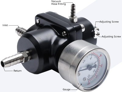
Basic functions and effects of injection pressure regulator
The main function of the injection pressure regulator is to maintain a constant pressure of fuel or liquid in the injection system.
For example, in a diesel engine, the IPR controls the oil pressure generated by the high-pressure oil pump through a solenoid valve. Thereby regulating the fuel pressure entering the injector. This regulation usually controlls by an electronic control module (ECM) or an engine control unit (ECU) according to engine operating conditions and driver needs.
Pressure regulation and stabilization
Reducing high-pressure inlet pressure (such as fuel, gas or liquid) to a stable low-pressure output (such as the pressure delivered to the injector), and automatically compensating for inlet pressure fluctuations or flow changes to keep the outlet pressure constant.
For example: When the engine is running, the fuel pressure regulator senses the changes in the intake manifold pressure through the vacuum diaphragm, dynamically adjusts the fuel rail pressure, keeps the pressure difference between the injector inlet and the manifold constant (usually about 3.0 bar), and ensures that the injection amount depends only on the injection time.
Flow matching
- Automatically adjust the opening according to downstream demand: when the flow demand increases, the opening is expanded to maintain pressure; when the demand decreases, the opening is reduced to avoid overpressure.
- In irrigation or pneumatic systems, flow adaptation is achieved by changing the throttle area (such as poppet valve, butterfly valve).
Safety protection
As a pressure relief device, when the pressure exceeds the set value, the excess fluid is directed back to the tank or storage tank through the bypass port to prevent system overpressure.
Improve system stability
Eliminate the impact of inlet pressure fluctuations (such as fuel pump pulsation, air source pressure changes) on downstream equipment, and ensure constant pressure during injection, combustion or irrigation.
Optimize control accuracy
- Maintain a constant pressure difference (such as between the fuel rail and the intake manifold), so that the ECU can manage the injection amount by accurately controlling the injection time, and improve the air-fuel ratio control accuracy
- In microinjection systems (such as cell injection), the air pressure regulator can control the liquid output from microliters to femtoliters, with an error of ≤50%.
Energy saving and equipment protection
- Reduce ineffective energy consumption: bypass reflux design (such as fuel system) to avoid pumping energy waste.
- Prevent high-pressure damage: protect downstream components such as nozzles and sensors, and extend equipment life.
Operating adaptability
Automatically compensate for load changes: for example, reduce fuel pressure when the engine is idling (high vacuum conditions), increase pressure when the load is large, and adapt to different operating conditions
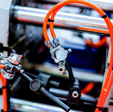
Working Principle
IPR usually adopts pulse width modulation (PWM) technology to adjust the hydraulic pressure by receiving electrical signals from the ECM.
For example, in the Ford Power Stroke diesel engine, the IPR installes at the rear of the high-pressure oil pump. And also changes the pressure range of the high-pressure oil by adjusting the opening and closing frequency of the solenoid valve. Thus to meet the needs of different working conditions.
Core component functions
- Sensing mechanism (such as diaphragm, piston): sense outlet pressure (Fo).
- Loading mechanism (such as spring, electromagnetic force): provide preset reference force (Fs).
- Control valve (such as valve core, ball valve): adjust the opening of the fluid channel.
Dynamic adjustment process
- When the outlet pressure drops (such as the flow demand increases): Fo < Fs → the loading force pushes the valve core to open a larger channel → the flow increases → Fo returns to balance.
- When the outlet pressure rises (such as the flow demand decreases): Fo > Fs → the fluid pressure pushes the valve core to close a smaller channel → the flow decreases → Fo returns to balance.
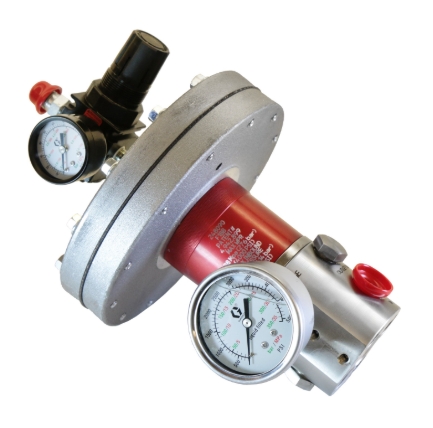
Structure and composition
The injection pressure regulator usually consists of the following parts:
- Solenoid valve: used to control the flow of high-pressure oil.
- Sensor: monitors the fuel pressure and feeds back the signal to the ECM.
- Regulating valve: adjusts the fuel pressure according to the instructions of the ECM.
Hydraulic system integration
The pressure regulator is part of the hydraulic system and works with the hydraulic pump, control valve (such as proportional flow valve, pressure valve), cylinder and oil tank
The hydraulic pump provides high-pressure oil flow, and the control valve (such as servo valve or proportional valve) adjusts the oil pressure and flow according to the electrical signal, thereby controlling the action of the injection cylinder and the clamping cylinder
Core control element
Pressure control valve
Directly adjusts the oil circuit pressure.
For example:The injection pressure is graded through the high and low pressure oil circuit switching valve (high pressure is used for initial filling, and low pressure is used for the pressure holding stage).
Proportional pressure valve
receives instructions from the electronic control system and dynamically adjusts the oil pressure to meet the needs of different process stages.
Servo mechanism
accurately adjusts the valve opening under the instructions of the electronic control system to achieve closed-loop control of pressure (such as the injection servo mechanism in).
Workflow and pressure control method
Electrical control system collaboration
The pressure regulator relies on the electronic control system (PLC or dedicated controller) to provide setting parameters.
The electronic control system monitors the pressure in real time through sensors (such as pressure sensors) and forms a closed-loop feedback with the regulator.
Multi-level pressure control
Medium and large injection molding machines usually provide three pressure modes: high pressure, low pressure, and high pressure to low pressure:
- High-pressure injection: In the initial stage, high-pressure oil is used to push the screw to quickly fill the cavity.
- Pressure holding stage: switch to low pressure, maintain pressure to prevent melt backflow and compensate for shrinkage.
- The pressure switching point is triggered by the screw position or injection pressure threshold (for example, the screw automatically switches when it reaches the set position).
Key control parameters
- Injection pressure: overcome the flow resistance of the nozzle, runner and cavity, which must be higher than the theoretical requirement for plastic molding.
- Pressure holding pressure: prevent product shrinkage and deformation, usually lower than the injection pressure.
- Back pressure: control the melt uniformity through the screw retreat resistance during the plasticization stage, too high will cause degradation.
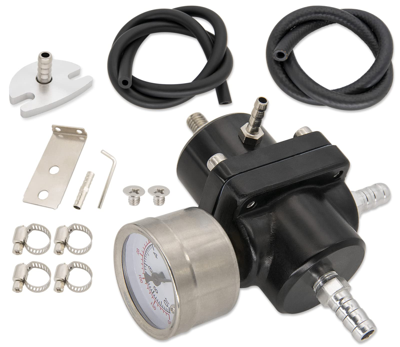
Application scenarios
Diesel engines
IPR is widely used in the high-pressure common rail system of diesel engines to adjust the injection pressure to improve fuel efficiency and combustion performance.
Other industrial applications
In some industrial systems, injection pressure regulators are also used to control the injection pressure of gas or liquid to ensure the stability and efficiency of the system.
Technical Features
High-precision regulation
Hyundai IPR is able to adjust fuel pressure in real time according to engine load and driving conditions, thereby optimizing fuel economy and emissions performance.
Durability and reliability
The high-performance IPR design focuses on durability and reliability, suitable for high-speed and high-load working environments.
The injection pressure regulator is an indispensable key component in modern fuel injection systems. It not only ensures that engines and other equipment can operate efficiently under various operating conditions by accurately controlling fuel pressure. At the same time, regular maintenance and timely replacement of faulty parts are essential to ensure its normal operation.