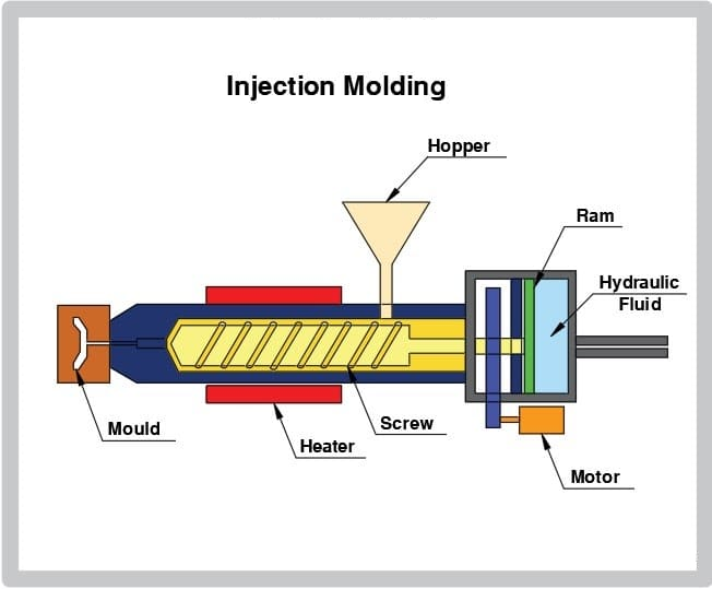
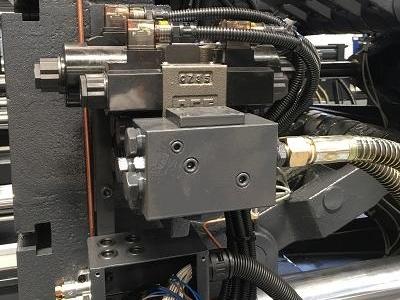
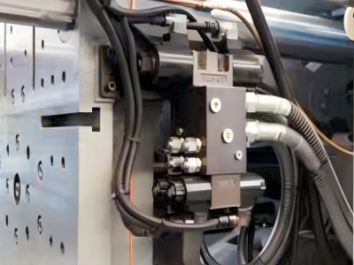
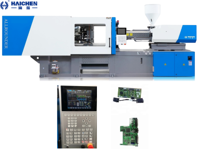
The hydraulic clamping cylinder structure usually consists of a piston, a piston rod, a cylinder body and a sealing ring, etc.
The hydraulic clamping cylinder is one of the core components of the clamping mechanism of the injection molding machine. Its main function is to provide clamping force through the hydraulic system. Thus to ensure that the mold remains stable during the injection process.
The structural design and functions of hydraulic clamping cylinders vary according to their application scenarios. Its core components include cylinder body, piston rod and piston, while hydraulic pump station, valves and other accessories are combined to achieve precise control. By optimizing material selection, manufacturing process and automation integration, hydraulic clamping cylinders can meet various industrial processing needs and ensure the safety and reliability of operation.
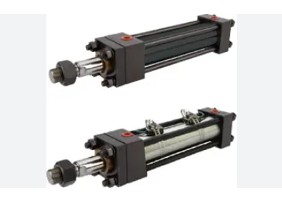
Basic structure of Hydraulic clamping cylinder structure
The hydraulic clamping cylinder is usually composed of a piston, a piston rod, a cylinder body and a sealing ring. The piston slides in the cylinder body, pushes the piston rod through the pressure of the hydraulic oil. Then to achieve the clamping action.
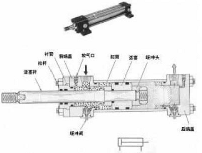
Cylinder Barrel
- Main structure, inner hole needs precision machining (surface roughness Ra=0.1–0.4μm), the material is mostly structural carbon steel or aluminum alloy, used to accommodate piston and hydraulic oil.
- The two ends are connected to the end cap by welding, bolts, flanges or threads to form a closed oil chamber.
Piston and Piston Rod.
Piston
Usually made of steel, cast iron or aluminum alloy, with a length of about 0.6–1.0 times the cylinder diameter, equipped with sealing rings (O-rings, V-belts, etc.) to prevent internal leakage.
Piston Rod
Solid or hollow steel, surface hardened and chrome-plated, one end is connected to the piston (fixed by a key or nut), and the other end transmits the clamping force.
Special design: Some clamping cylinders use L-shaped pistons and cylinder barrels to adapt to space restrictions or rotation clamping requirements.
End Caps and Guide Sleeve
- End Caps: Divided into Cap End and Gland End, they bear high pressure and support the piston rod.
- Guide Sleeves: Guide the movement of the piston rod (partial designs are directly guided by the end caps) to reduce friction.
Sealing System
- Dynamic seal (between the piston rod and the guide sleeve): Use a combined seal ring (such as O-ring + Y-ring) and a dust ring.
- Static seal (between the cylinder barrel and the end cap): Ensure that there is no leakage of high-pressure oil.
Buffer and Vent
- Buffer: Prevent impact at the end of the stroke and reduce noise (such as stepped cylinder barrel design).
- Vent: Expel air from the cylinder to avoid creeping or shaking during low-speed movement.
In addition, the design of the hydraulic clamping cylinder may also include auxiliary components such as a booster mechanism and a regulating valve to improve the stability and accuracy of the clamping force.
Working principle
The working principle of hydraulic clamping cylinder is based on the pressure transmission of hydraulic oil. When the hydraulic pump provides high-pressure hydraulic oil, the hydraulic oil enters the cylinder through the pipeline and pushes the piston to move. The piston rod connects to the pull rod, driving the moving template to move, thereby realizing the clamping action.
During the clamping process, the hydraulic oil enters the cylinder through the one-way valve to complete the clamping action. During the mold opening process, the hydraulic oil will discharge through the pressure relief valve to release the clamping state.
Basic hydraulic principles
- According to Pascal’s Law: the pressure of a closed fluid is transmitted evenly, and a small input force can output a large output force.
- Single-acting cylinder: Hydraulic oil drives one-way movement, and the return stroke relies on spring/gravity (such as clamping release).
- Double-acting cylinder: Hydraulic oil alternately enters the two chambers to achieve bidirectional movement (more common in clamping cylinders).
Hydraulic clamping cylinder Clamping process
- Hydraulic oil input: High-pressure oil enters one side of the cylinder body (such as the left chamber) to push the piston axially.
- Force transmission and amplification:
The piston pushes the hinge rod or the elbow connecting rod to amplify the output force (up to several times the input force) through the lever principle. For example: The rectangular groove of the rodless piston drives the slider, driving the hinge rod to push the clamping rod to clamp the workpiece - Clamping lock:
The elbow mechanism is self-locking at the dead point position, and there is no need to continuously supply pressure to maintain the clamping force. - The size of the clamping force is controlled by adjusting the oil pressure or the mold position.
Release process
- The hydraulic oil is switched to another chamber (such as the right chamber), the piston moves in the opposite direction, and the clamping block is retracted through the connecting rod mechanism.
- Some designs use spring-assisted reset.
Key features
- Force-enhancing effect: The lever/hinge mechanism significantly amplifies the clamping force, allowing the use of smaller cylinder diameters or low-pressure systems.
- Self-locking capability: The toggle mechanism mechanically locks at the dead point, which is energy-saving and safe.
- Structural optimization:
The rodless piston design reduces radial forces and reduces cylinder wear.
Symmetrical hinge layout balances forces and improves system rigidity. - Safety and maintenance
Hydraulic clamping automatically releases when power is off.
External clamping mechanism facilitates maintenance.
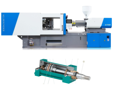
Optimization design
In order to improve the performance of hydraulic clamping cylinder, researchers have proposed a variety of optimization design methods. For example, by adjusting the diameter and rod diameter ratio of the hydraulic cylinder, energy consumption can be effectively reduced and clamping accuracy can be improved.
In addition, the differential combination cylinder design can use the large cylinder barrel to achieve differential movement during the rapid mold opening and closing stage, thereby improving the mold closing speed and accuracy.
Finite Element Analysis (FEA) and Parametric Modeling
- Use ANSYS and other software to establish parametric models, and perform stress and deformation analysis on components such as pistons, piston rods, and cylinder walls. After optimization, the maximum equivalent stress is reduced and the load distribution is more uniform, reducing weight while increasing stiffness and strength.
- Generate design points through the response surface method, combine Latin hypercube sampling to optimize variables (such as inner diameter/outer diameter), and improve the safety factor.
Multi-objective optimization design
Take safety (maximum equivalent stress) and weight (volume) as the dual objectives, introduce constraints (boundary constraints, installation length, maximum cylinder diameter, etc.), and use genetic algorithms to solve the optimal solution.
Sealing structure
- Double O-ring gapless design can significantly improve the sealing effect. The seal groove width/depth is optimized through the surrogate model, and the contact pressure is stabilized at 4.38–7.28 MPa.
- The rubber material is assumed to be isotropic, and the model is simplified to reduce the amount of calculation.
Connection and support structure
- The injection molding machine clamping cylinder adopts n-type rear-end connection support to improve the force imbalance of the four-cylinder system and reduce deformation.
- Marine hydraulic pipe clamps need to resist torsional force, optimize the frame design (such as 100×6 SHS frame) and select high lateral force cylinders (415.9 kN).
Improved mechanism design
- Toggle clamping can reduce input force, and the force amplification effect is verified by mathematical models and CAD.
- Lever clamping mechanism needs to control the action speed (install flow valve) to avoid clamping the workpiece during swinging.
Energy consumption and efficiency improvement
- Gas-liquid booster cylinder (such as SIMITCH) combined with mechanical spring reset reduces energy consumption; pre-compression oil chamber maintains constant pressure, suitable for high-frequency operations.
- Hydraulic clamps reduce clamping time by more than 30%, and CAE optimized layout can minimize workpiece deformation.
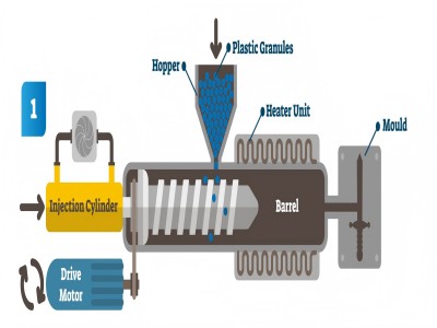
Application and innovation
Hydraulic clamping cylinder is widely used in injection molding machines, especially in high-precision and high-speed injection molding. In addition, some new injection molding machines also adopt external superchargers and automatic adjustment technology to further improve the stability of clamping force and mold processing quality.
Hydraulic-mechanical hybrid clamping system
Combines the advantages of hydraulics and mechanics: first use the hydraulic cylinder to quickly move the mold plate, and then maintain high pressure (>1000 tons clamping force) through mechanical locking, combining high tonnage and energy saving).
Typical workflow
- → The hydraulic cylinder pushes the moving mold plate to close the mold
- → Mechanical components (such as elbows) lock the position
- → High-pressure hydraulic cylinder applies the final clamping force
Self-locking hydraulic cylinder
- Supports fast mold change: can be permanently installed or plugged in and out through slots, equipped with interlocking sensors to prompt the working status.
- High clamping force: a single cylinder provides 127 kN clamping force, and multiple cylinders can be connected in parallel to expand capacity.
Rotary and lever hydraulic cylinders
- Rotary hydraulic cylinder: The clamping arm can be rotated 80° to facilitate complex angle operations.
- Lever hydraulic cylinder: compact design adapts to multi-directional installation and supports height adjustment.
Application
Large equipment
Hydraulic mechanical clamping has become the mainstream of equipment >1000 tons, and the structure is optimized through high-rigidity five-point elbow (finite element analysis design).
Precision molding
Hybrid drive technology improves the molding stability of thin-walled parts.
Quick mold change system
Standardized hydraulic cylinder interface (such as DIN standard slot) supports mold replacement within 10 minutes.
Intelligent upgrade
Integrated pressure sensor monitors clamping force in real time, and linkage control system dynamically adjusts.
Maintenance and fault analysis
Maintenance and fault analysis of hydraulic clamping cylinders are also important parts of their design. Incorrect oil distribution, insufficient oil filling, and the presence of bubbles may lead to deterioration of the performance of the hydraulic system.
In addition, improper installation of the hydraulic control valve may also cause failure of the hydraulic system.
Seals and lubrication
Replace seals regularly: prevent hydraulic oil leakage.
- Seal failure is one of the main causes of cylinder failure and needs to be replaced according to the equipment manual cycle
- Lubricate sliding parts: Keep the movable plate slide rail, sliding seat and toggle hinge clean and lubricated, otherwise it will accelerate wear. Check the lubrication status every week.
Hydraulic system maintenance
Hydraulic oil management:
- Maintain sufficient oil level and regularly check oil quality (pollution or aging will cause unstable system pressure)
- Control oil temperature ≤60℃, high temperature will accelerate seal aging and reduce oil viscosity.
- Valve and filter cleaning: Clean hydraulic valves regularly to prevent impurities from getting stuck.
Operation specification
- Avoid overpressure use: The clamping pressure is strictly prohibited to exceed the equipment rating, otherwise it will cause deformation of the cylinder or seal bursting.
- Mold closing stroke optimization: Adjust the mold closing end position to a moderate distance to reduce the impact load during high-speed mold closing.
- No rapid mold adjustment: Disable ultra-high speed mode when adjusting the mold to prevent mechanical overload.
Structural maintenance
- Regularly check the support structure: For two-plate cylinders, the stress and deformation of the rear-end connectors need to be monitored
- Stiffness calibration: Mechanical stiffness (template/tie rod) and hydraulic stiffness (cylinder position) need to be coordinated to avoid mold rebound
The structure and working principle of the hydraulic clamping cylinder of the injection molding machine involve many aspects, including basic structure, internal circulation design, working principle, optimization design, application innovation, maintenance and fault analysis. These characteristics make the hydraulic clamping cylinder play a vital role in the injection molding machine, providing an important guarantee for the precision and efficiency of injection molding.