A tie bar or in other words known as a tie rod is a structural unit used as a tie. Tie bars are capable of carrying only tensile loads.
In general, because the ratio of the typical tie bar’s length to its cross-section is usually very large, it simply buckles under the action of compressive forces. The working strength of a tie rod is the product of the allowable working stress and the bar’s minimum cross-sectional area.
The diameter of the tie rod is an indicator of the size and strength of the clamping component of the injection molding machine. We usually use precision machinery to perform multi-point measurements to determine its specific number.
Below we will analyze for you the various methods we use to measure and calculate the tie rod diameter of an injection molding machine.
Injection molding machine tie rod diameter measurement and calculation method
The tie bar diameter in injection molding machines depends on clamping force, material strength, and safety factors. Here’s a step-by-step guide:
- Determine Clamping Force (F)
The clamping force is specified in the machine’s technical data (e.g., 1000 kN or 1,000,000 N). - Select Allowable Material Stress (σ)
Tie bars are typically made of high-strength alloy steel (e.g., 40Cr or En19/4140). The allowable stress (σ) is generally ≤250 MPa (250×10⁶ Pa), adjusted based on heat treatment and safety standards. - Calculate Minimum Diameter Using Tensile Stress Formula
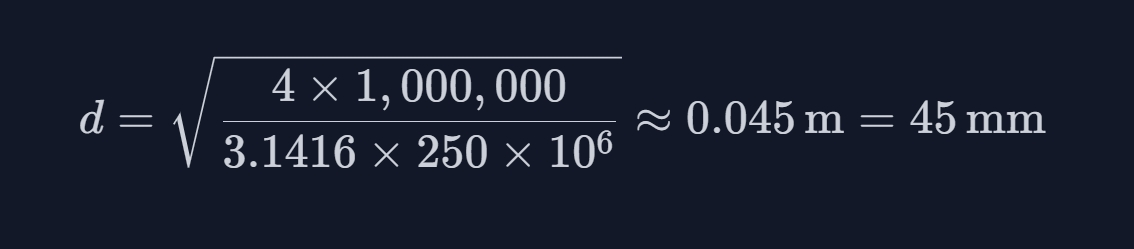
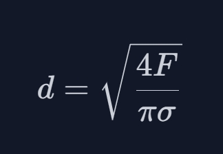
The formula for tie bar diameter under tensile stress is:Example Calculation (F = 1,000,000 N, σ = 250 MPa):
 d=4×1,000,0003.1416×250×106≈0.045 m=45 mm
This aligns with industry standards (e.g., 45–50 mm for a 1000 kN machine).
- Validate Against Machine Specifications
Cross-check with manufacturer data. For instance, a 65 kN clamping force machine may use 50 mm tie bars, while a 108 kN machine might require 65 mm. Scale calculations proportionally for larger forces. - Apply Safety Factors and Installation Requirements
Include a safety factor (1.5–2) and ensure compatibility with mold plate mounting holes (e.g., 110 mm or 125 mm adapters mentioned in specifications).
The critical formula is.
Always combine theoretical calculations with machine-specific data and safety standards. For a 1000 kN machine, tie bars typically range from 45–50 mm in diameter.
What is the injection molding machine tie bar diameter?
The tie bar diameter of an injection molding machine is not a standardized value and is typically not explicitly listed in general specifications. Based on available information and industry practices:
- Key Parameter Focus:
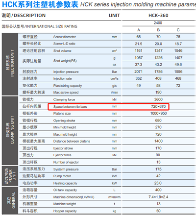
Most documentation emphasizes tie bar spacing (the inner distance between tie bars) rather than tie bar diameter. For example, tie bar spacing values like 420 mm × 420 mm or 470 mm × 470 mm are common for mold installation constraints. - Tie Bar Design and Material:
Tie bars are usually made of high-strength alloy steel (e.g., En19/4140) and undergo heat treatment for durability. While their diameter is critical for structural integrity, it is often proprietary or varies by manufacturer and machine tonnage. Larger machines (e.g., 1000+ ton clamping force) will naturally have thicker tie bars compared to smaller machines. - How to Find the Diameter:
- Manufacturer Specifications: Contact the machine manufacturer directly for technical drawings or detailed specs.
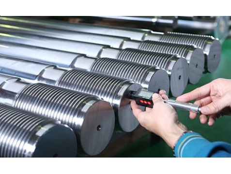
- Physical Measurement: For existing machines, measure the diameter using calipers (commonly ranges from 50 mm to 200+ mm depending on machine size).
- Engineering Calculations: Diameter correlates with clamping force and tie bar material strength, but this requires specialized knowledge.
- Why It’s Rarely Disclosed:
Tie bar diameter is often considered a design-specific detail. Manufacturers prioritize specifications like clamping force, platen size, and tie bar spacing, which are more relevant for mold compatibility.
Haichen High Strength Tie bar for Injection Molding Machine
The high-strength tie bar design of Haichen injection molding machines reflects its technological advantages in structural optimization and material processing. Key features include:
- High Strength & Reliability
- Dynamic Performance & Lubrication
- Warranty & Maintenance
- Versatility & Scalability
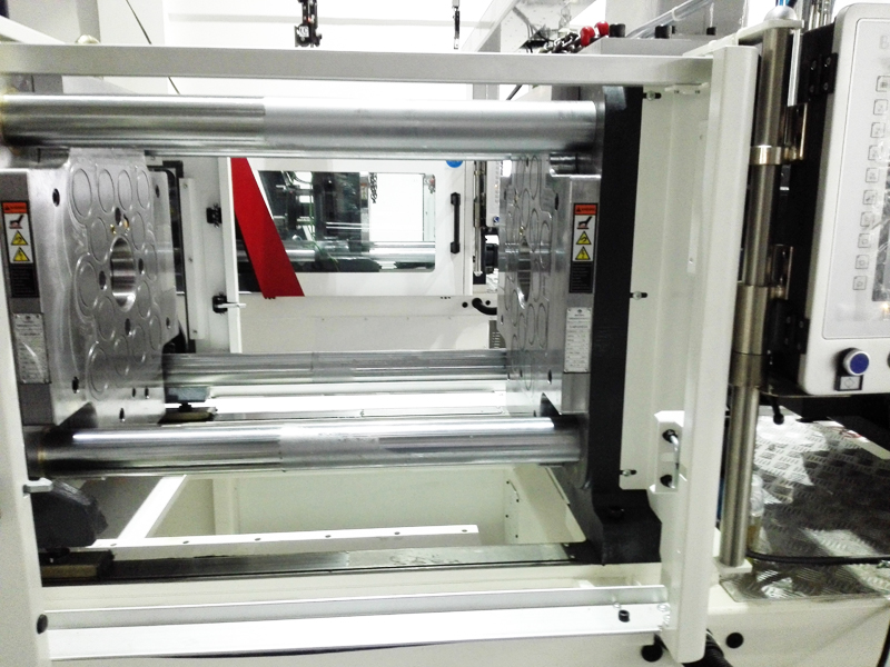
High Strength & Reliability
- Special Material Treatment: Tie bars undergo advanced heat treatment and surface hardening processes to enhance tensile strength and fatigue resistance.
- Structural Optimization: Finite Element Analysis (FEA) is applied to optimize the tie bars and clamping unit. Innovations like the hollow spherical fixed platen structure and box-type platen connections significantly improve rigidity and anti-deformation capabilities, ensuring stability during clamping.
- Adjustable Tie Bar Distance: Tailored spacing for different machine tonnage (e.g., 360×360mm for HCK100 vs. 870×870mm for HCK600) accommodates diverse mold sizes and production needs.
Dynamic Performance & Lubrication
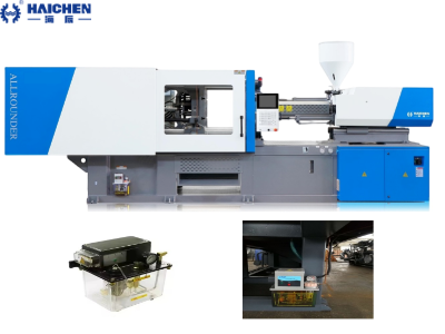
- Five-Point Double-Crank Mechanism: The ramp-row five support-point double crank web structure ensures dynamic balance during high-speed mold opening/closing, minimizing vibration and stress concentration.
- Centralized Lubrication System: Reduces friction between tie bars and platens, extending service life.
Warranty & Maintenance
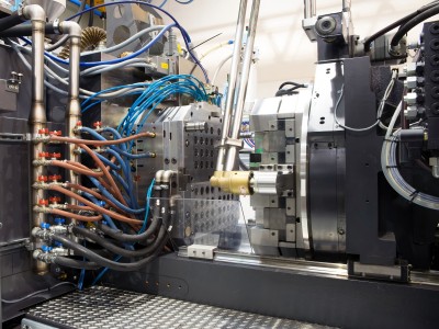
- 24-Month Warranty: Core mechanical components like tie bars are covered for 24 months, excluding damage caused by improper mold alignment or unauthorized disassembly.
- Low-Pressure Mold Protection: Built-in sensors halt operations under abnormal pressure to prevent overloading.
Versatility & Scalability
- Large Mold Compatibility: Spacing up to 970×920mm (e.g., HCK700) supports oversized molds for automotive parts, appliance housings, etc.
- Hydraulic Mold Adjustment: Gear-driven systems enable rapid tie bar spacing adjustments for faster mold changes.
By the end

Haichen combines material science, structural simulation, and intelligent control to deliver tie bars with exceptional load-bearing stability and adaptability. Users should select tie bar spacing and clamping force (e.g., 150-ton for HCk150, max mold height 450mm) based on mold size and product requirements, while adhering to operational guidelines to maximize equipment longevity.
For precise values, Let Haichen injection molding machine’s technical engineer team answer more questions for you.