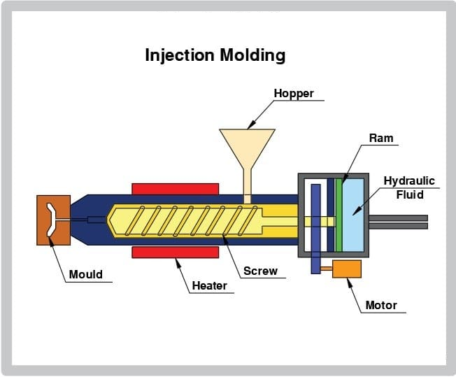
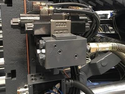
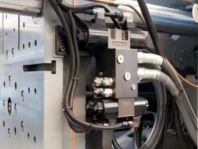
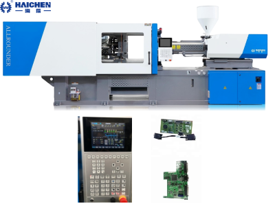
Tie Bar of the injection molding machine is a structural component that plays a key role in the injection molding process.
It is mainly used to connect and fix the upper and lower templates of the mold, ensuring that the mold can be stably closed and withstand the clamping force under high pressure.
The injection molding machine pull rod not only plays a crucial mechanical role in the molding process.
But also plays an important role in mold guidance, demolding, production efficiency and environmental protection.
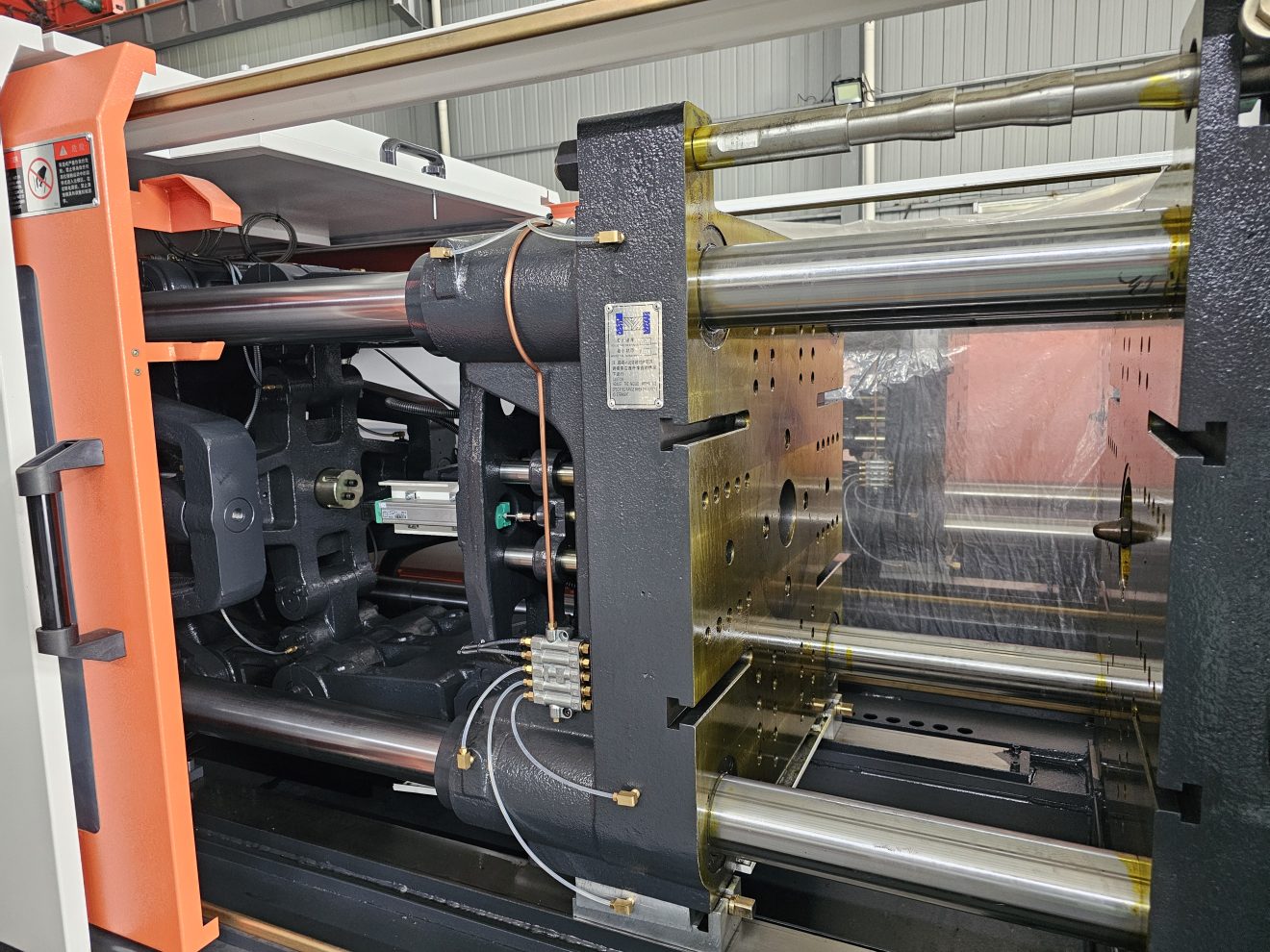
The structural composition of the Tie Bar
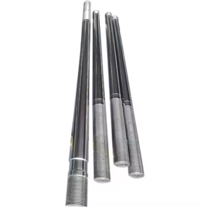
Threaded section: Threads are processed at both ends and fixed to the tailplate and the fixed template through nuts.
Smooth section: In coordination with the template guide holes, the surface roughness is ≤0.8µm, and the straightness is ≤0.05mm/m.
Stress relief groove: Key innovative design to reduce stress concentration (such as head plate relief groove, mold adjustment relief groove) and lower the risk of fracture.
Optimization plan: The ratio of the unloading groove diameter to the pull rod diameter needs to be precisely designed through finite element analysis (FEA).
The role of the pull rod in the injection molding process
Transmitting clamping force
The tie rod is an important structural component connecting the moving template and the fixed template.
It is used to transmit clamping force during the clamping process, ensuring that the mold can be tightly closed under high pressure.
Thereby preventing the molten plastic from overflowing under high pressure.
Guidance and support
During the injection molding process, the pull rod not only serves to transmit force but also provides guidance and support.
Especially in two-plate injection molding machines, the pull rod serves as a guiding component for the moving template.
Ensuring that the moving template moves smoothly during the mold opening and closing process and preventing mold damage caused by deviation or vibration.
Preventing mold damage
During the mold locking process, the pull rod is subjected to tensile and bending stresses.
If the design is improper or the material is fatigued, it may cause the pull rod to break, thereby affecting the stability of the mold.
Therefore, the design and material selection of the pull rod are of vital importance to ensure its reliability and safety during long-term use.
Auxiliary demolding
Moreover, in some mold designs, designers also utilize the pull rod for auxiliary demolding.
Particularly when extracting the main runner material from the mold is essential.
For example, in the side gate gating system, the material pull rod actively pulls out the solidified material in the main runner.
Preventing the solidified material from adhering to the mold and ensuring that the runner and the product remain on the moving mold side.
Optimizing mold installation
The spacing and position of the pull rods have a significant impact on the external dimensions of the mold.
If the length dimension of the mold exceeds the spacing of the pull rods, the possibility of the mold rotating within the pull rod space must be considered.
Otherwise, it may be necessary to adjust the mold shape or replace the injection molding machine.
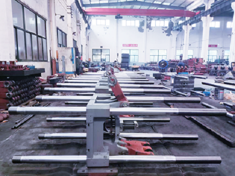
The basic role and design requirements of the Tie Bar
Functional core
The tie rod serves three primary functions: connecting the front and rear platens.
Bearing the tensile stress from the clamping force, and providing a guiding reference for the moving platen.
Consequently, these structural elements must be designed with high strength, stiffness, and fatigue resistance in mind.
Design requirements
To reduce stress concentrations, cross-section changes require arc transitions.
Therefore, high-precision machining must be applied to the surface.
To ensure the hardness and low roughness of the guide surface.
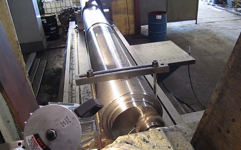
Tie Bar materials
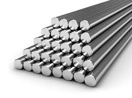
- Aluminium alloy
- Stainless steel
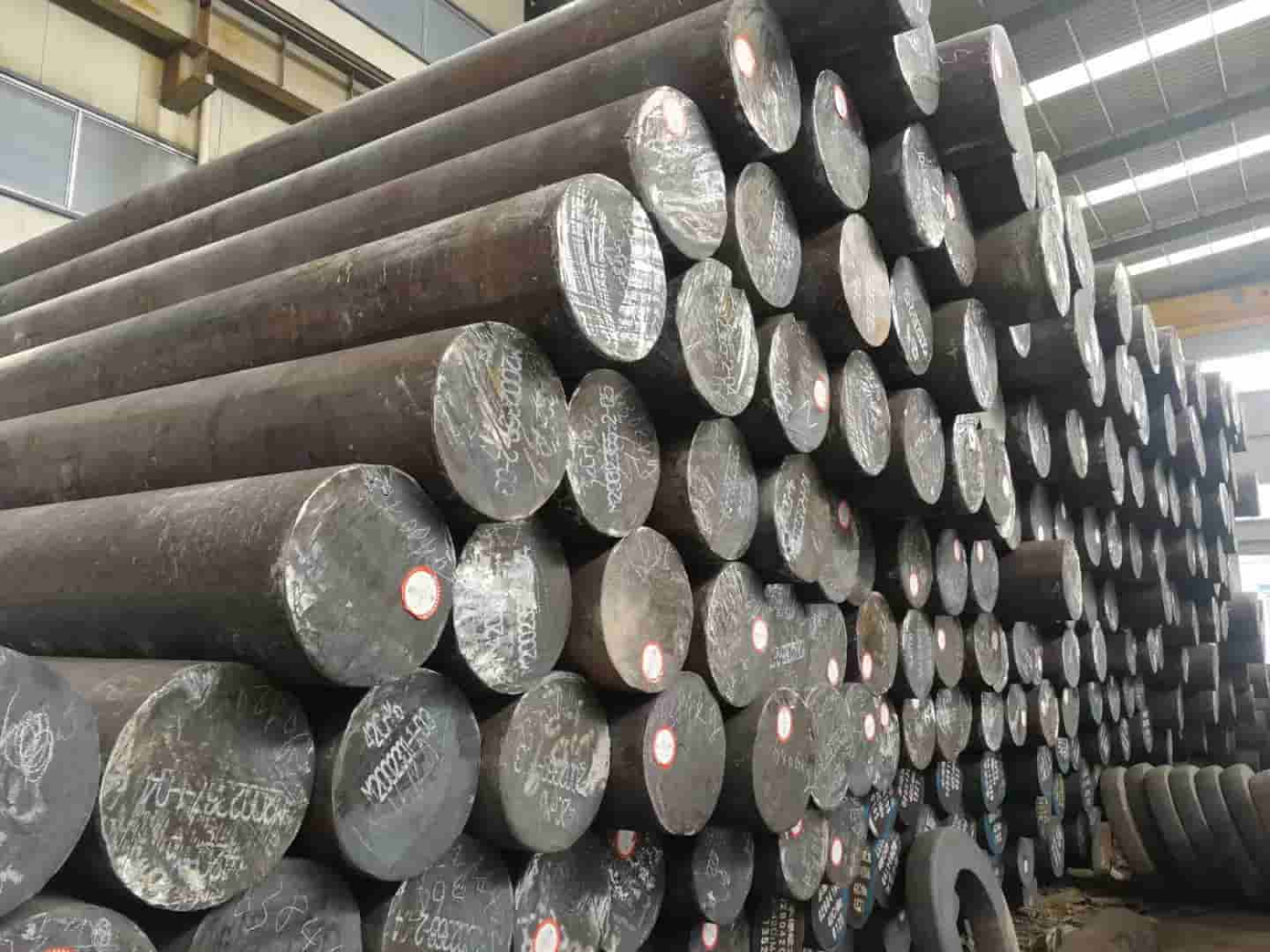
- Carbon steel
- Tool steels
Alloy tool steel
Aluminium alloy
Light weight (density 2.7 g/cm³), high corrosion resistance, easy machining.
But low hardness and strength (tensile strength approx. 200-300 MPa).
Stainless steel
Excellent corrosion resistance (including Cr≥16%), medium strength (tensile strength 500-700 MPa), suitable for wet or corrosive environments.
No additional anti-rust treatment is required, but the processing cost is high.
Carbon steel
Low cost (about 1/3 of the price of alloy steel), medium strength (tensile strength 370-510 MPa), hardness 30-35 HRC.
Small molds or low-load parts, but regular anti-rust treatment is required.
Alloy tool steel
Excellent strength at high temperature (high hardness at 500°C), good heat fatigue resistance.
Hardness HRC40-45, suitable for die-casting molds and injection molds.
Regular surface nitriding is required to enhance wear resistance.
Tool steels
Comprehensive performance balance, hardness HRC50-55,
Moderate wear resistance and toughness, suitable for complex mold structures.
Causes of Tie Bar breakage and maintenance strategies
The main cause of fracture
Fatigue failure: Alternating stress leads to the propagation of microcracks at the root of the thread.
Overload breakage: Blindly increasing the clamping force to solve the flash problem.
Design flaws: Sudden change in shaft diameter, improper proportion of unloading grooves, and too small fillet.
Assembly error: The lengths of the four pull rods are inconsistent, and the preload of the nut is uneven.
Solutions and preventive measures
Design optimization: Avoid sudden changes in shaft diameter and adopt large fillet transitions
The diameter ratio of the unloading trough was verified by FEA.
Material upgrade: The fatigue life of 31CrMoV9V steel is superior to that of 42CrMo4V.
Process control: Quenching and tempering treatment + chromium plating, hardness ≥HRC45.
Calibrate the length of the pull rod during assembly.
Usage specification: When flash occurs, prioritize leveling the mold rather than increasing the clamping force.
Lubricate the pull rod nut regularly.