To solve servo drive overload in injection molding, first diagnose the root cause, which can be mechanical, electrical, or parameter-related.
Solutions involve preventative maintenance, optimizing VFD parameters, monitoring load conditions, improving cooling, and correctly sizing the servo system for the application.
When the servo driver of an injection molding machine is overloaded, the best balance can be achieved by choosing hardware with high overload capacity and optimizing parameters.
Hardware selection and parameter adjustment need to be carried out in coordination, combined with testing and maintenance, to ensure the stability and reliability of the system under high loads.
Servo drive overload is a common failure in injection molding that can lead to equipment downtime, reduced productivity, and even hardware damage.
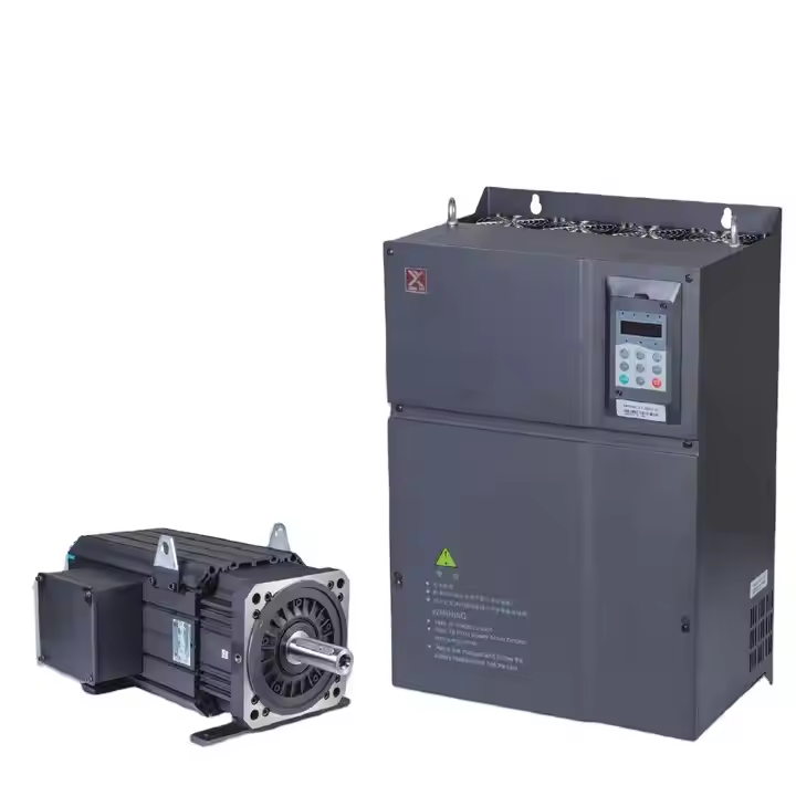
Servo drive overload cause analysis and diagnostic methods
- Excessive mechanical loads
- Improper setting of electrical parameters
- Hardware Failure
- Environmental factors
Excessive mechanical loads
Causes: The load exceeds the carrying capacity of the drive due to increased mold resistance of the injection molding machine.
Stagnation of the transmission mechanism, deviation of the coupling or poor gear engagement.
Diagnosis: No-load operation test: If the no-load is normal, there is an abnormal load in the mechanical system.
Check for wear or loose installation of components such as couplings, pulleys, bearings, etc.
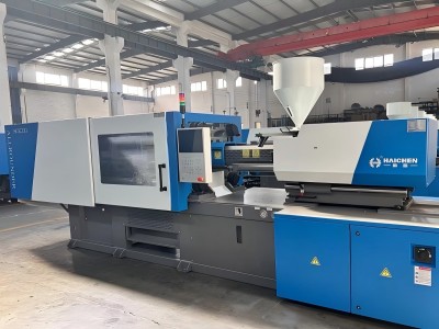
Improper setting of electrical parameters
Reason: Unreasonable settings of parameters such as current limit, speed loop gain.
And electronic gear ratio lead to a mismatch between the driver output and the load.
Diagnostics: Read the alarm code (e.g. overload alarm 0xFF02) via the drive panel or host computer software.
Check whether the current limit value (for example, T2-08/T2-09) is consistent with the motor nameplate parameter.
Hardware Failure
Causes: Damaged power module, broken or poor contact of UVW line, short circuit in motor winding.
Diagnostic: Use a multimeter to detect UVW line on-off and phase sequence.
Use the oscilloscope to observe whether the output waveform of the power module is abnormal.
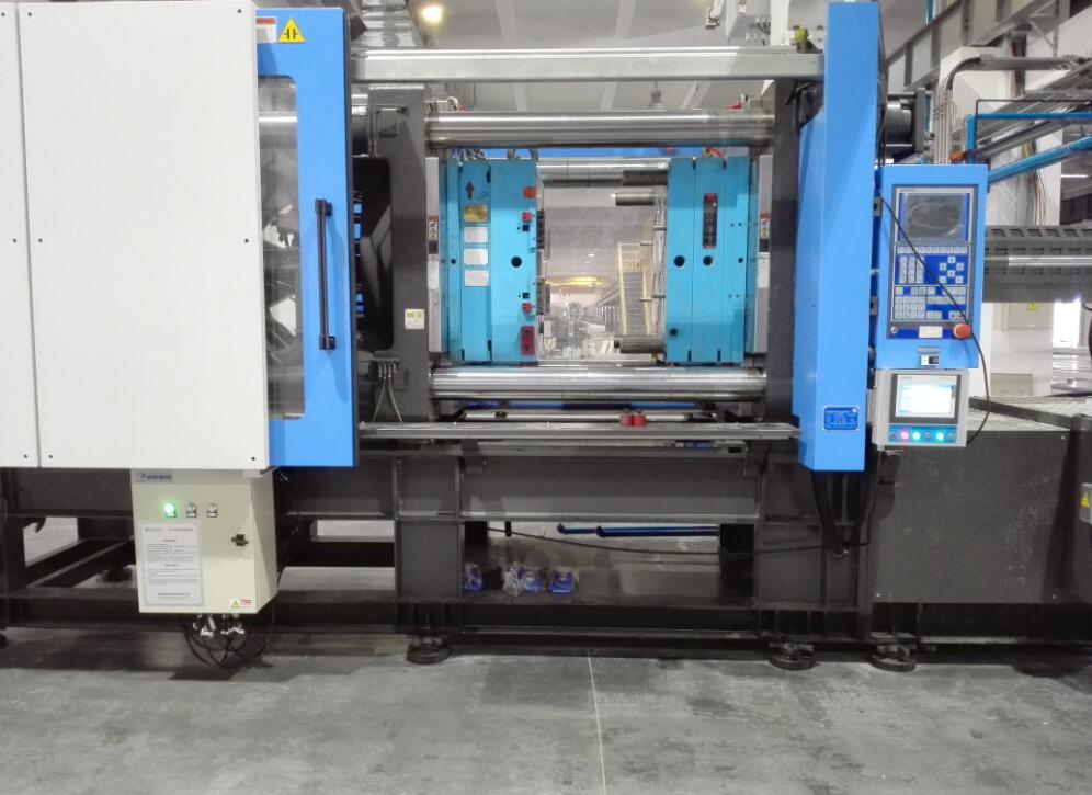
Environmental factors
Cause: Poor heat dissipation causes the driver temperature to be too high, triggering overload protection.
Malfunction caused by fluctuations in power supply voltage or electromagnetic interference.
Diagnostics: Monitor the drive surface temperature (normal should be below 55°C).
Use a multimeter to check the stability of the power supply (fluctuations should be controlled within ±10%).
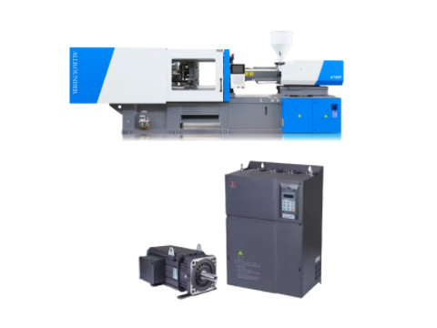
Servo drive overload handling measures and optimization strategies
- Adjustment of mechanical systems
- Electrical parameter tuning
- Gain Adjustment
- Process Parameter Optimization
- PID parameter adjustment
- Environmental Adaptability Improvement
- Install a noise filter
Adjustment of mechanical systems
Load optimization: Reduce mold drag or replace a higher power motor (e.g. upgrade from a 7.5kW motor to an 11kW motor).
Lubricate transmission parts regularly and repair worn bearings or gears.
Coupling calibration: Ensure that the coaxiality error between the motor shaft and the equipment system is ≤ 0.05mm to avoid additional torque caused by offset.
Electrical parameter tuning
Current & Overload Protection Settings:
Adjust the rated current (T2-04_05) and overload factor (e.g. 150% rated current for 60 seconds) according to the motor nameplate.
Optimize the electronic gear ratio (it is recommended to restore the factory default value to avoid resonance caused by setting too large).

Gain Adjustment
Adjust the position loop gain (P gain) and speed loop gain (V gain).
To ensure that the response speed is balanced with stability (e.g., the P gain is increased from 2000 to 2500).
Notch filter is enabled to suppress mechanical system resonances (50-500Hz frequency adjustment range is recommended).
Process Parameter Optimization
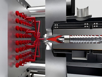
Vector Control Technology: High-performance vector control algorithms (such as closed-loop control of IS580 series drives).
Are used to optimize the accuracy of injection molding speed and pressure maintenance, and reduce load abrupt changes.
PID parameter adjustment
PID parameter of pressure loop: overshoot control below 3 bar to improve the stability of pressure holding.
Flow control: Extend the working range of the motor through the weak field control technology to improve the system response speed.
Environmental Adaptability Improvement
Thermal management: Install a cooling fan or water cooling system.
To ensure that the surface temperature of the driver ≤ 55°C (e.g. Hi-U series liquid cooling models).
The upper and lower spacing of ≥ 100mm is reserved in the control cabinet to optimize the air duct design.
Install a noise filter
Install a noise filter (e.g. Schaffner FN series) at the input of the power supply to suppress high-frequency interference.
Use shielded cables and ground them separately to avoid the control signal lines being parallel to the power lines.