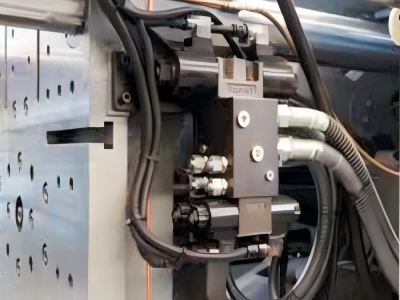
The following steps should be followed when installing tie rods on an injection molding machine:Before installation, clean the tie rod holes with gasoline, wipe them clean, and then apply grease. Before installation, clean the new tie rods and inspect them for damage.Measure the lengths of the remaining three tie rod bolts and average them: Position the mold adjustment bolts at the average point.When the gears are properly engaged, use a copper rod to push the tie rods into the holes from the rear plate. Note: The tie rods should move parallel to each other; special care should be taken when installing the dust seals.
The injection molding machine must operate in a balanced state; otherwise, the equipment will not operate stably and component damage may occur. A comprehensive inspection should be performed before starting the machine: verifying balance, checking lubrication conditions, and tightening bolts.
A high-quality injection molding machine requires excellent machine design, high-quality mechanical components, sophisticated assembly workmanship, and excellent balance. Tie rods are a key component of the machine, and their maintenance is crucial.
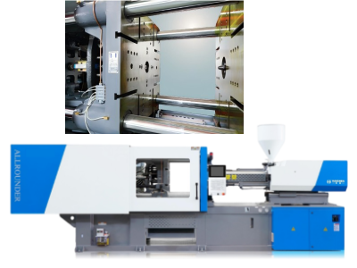
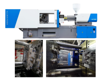
Tie bars are critical components of an injection molding machine, providing structural support and maintaining clamping force during operation.
Proper installation ensures machine stability, mold alignment, and longevity. Below is a detailed guide for tie bar installation, including tools, steps, and safety precautions:
Tools and Materials Required
- Hydraulic jack or tensioning device
- Torque wrench (calibrated)
- Dial indicator or laser alignment tool
- Lubricant (anti-seize compound)
- Thread cleaner/wire brush
- Manufacturer-specified tie bar nuts and washers
- Alignment rods or dummy bars (optional)
- Personal Protective Equipment (PPE): gloves, safety glasses
Pre-Installation Preparation
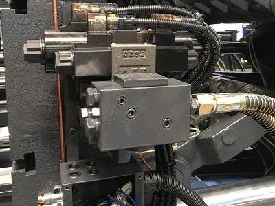
- Inspect Components:
- Check tie bars for bends, cracks, or thread damage.
- Ensure machine platens and frames are clean and free of debris.
- Level the Machine:
- Use a precision level to ensure the machine base is horizontal.
- Verify Thread Compatibility:
- Confirm tie bar threads match the nuts and machine platens.
Installation Steps
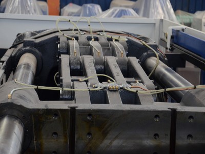
- 1: Insert Tie Bars
- Carefully slide the tie bars through the fixed and moving platens.
- Use alignment rods or dummy bars (if available) to temporarily hold the platens in position.
- 2: Lubricate Threads
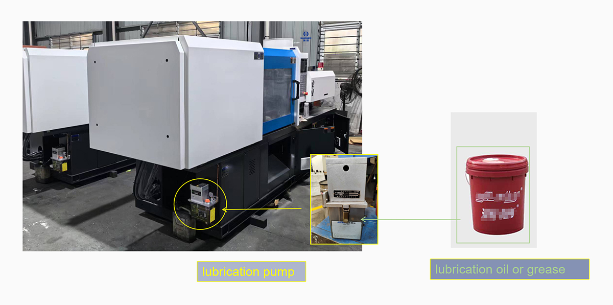
- Apply anti-seize lubricant to tie bar threads to prevent galling and ensure smooth tensioning.
- 3: Install Nuts and Washers
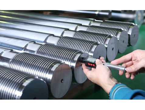
- Place washers and hand-tighten nuts on both ends of each tie bar.
- Ensure nuts are threaded evenly to avoid cross-threading.
- 4: Initial Tensioning
- Use a hydraulic jack or tensioning device to apply 10–20% of the recommended torque.
- Follow a star pattern (similar to wheel lug nuts) to tension tie bars evenly.
- 5: Final Torque Application
- Gradually increase torque to the manufacturer’s specification (typically 50–70% of tie bar yield strength).
- Example torque values (varies by machine tonnage):
| Machine Clamping Force | Torque per Tie Bar |
|---|---|
| 100 tons | 2,000–3,000 Nm |
| 500 tons | 8,000–12,000 Nm |
| 1,000 tons | 15,000–20,000 Nm |
- Step 6: Check Parallelism
- Use a dial indicator or laser alignment tool to ensure platens are parallel (tolerance: ±0.05 mm/m).
- Adjust tie bar tension if misalignment exceeds specifications.
Post-Installation Checks
- Clamping Force Test:
- Run the machine at maximum clamping force to verify tie bar stability.
- Vibration Test:
- Monitor for abnormal vibrations during operation.
- Re-Torque After Break-In:
- Recheck torque after 24–48 hours of operation, as initial settling may loosen nuts.
Safety Precautions
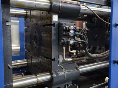
- Avoid Over-Tightening: Excess torque can stretch or fracture tie bars.
- Use Proper Lifting Equipment: Tie bars are heavy (100–500 kg each).
- Follow Manufacturer Guidelines: Adhere to specified torque and tension values.
Common Issues & Solutions
| Issue | Cause | Solution |
|---|---|---|
| Uneven Clamping Force | Misaligned or unevenly tensioned tie bars. | Re-torque in a star pattern; check parallelism. |
| Thread Stripping | Cross-threading or dirty threads. | Clean threads; replace damaged components. |
| Tie Bar Stretch | Over-tensioning or material fatigue. | Replace tie bars; adhere to torque limits. |
Maintenance Tips
- Regular Inspections: Check for cracks, corrosion, or thread wear every 6 months.
- Lubrication: Reapply anti-seize compound during maintenance.
- Alignment Checks: Verify platen parallelism annually.
Key Takeaways
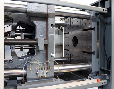
- Proper tie bar installation ensures even load distribution, preventing platen deflection and mold damage.
- Always use calibrated tools and follow manufacturer torque specifications.
- Post-installation alignment and tension checks are critical for long-term machine performance.
For detailed torque values and machine-specific guidelines, consult the manufacturer’s manual or contact technical support.
What is injectiontie bar distance?
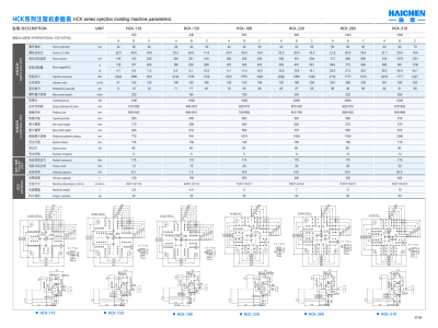
Injection Tie Bar Distance refers to the horizontal and vertical inner spacing between the tie bars that connect the platens in an injection molding machine or die-casting machine. This critical parameter determines the maximum allowable mold size and installation compatibility. Key details include:
- Definition and Importance
- Technical Specifications
- Mold Design Considerations
Definition and Importance
- Expressed in millimeters (e.g., 470×430 mm, 730×730 mm), it defines the workspace for mold installation. For example:
- A mold lowered vertically must have a width smaller than the horizontal tie bar distance.
- A mold inserted sideways must have a length smaller than the vertical tie bar distance.
- Safety clearance: Small molds require ~25 mm per side; large molds need ~50 mm to avoid collisions with tie bars during installation.
Technical Specifications
- Varies significantly across machines:
- BOY 125 E: 470 mm (horizontal)
- MA1600: 470×470 mm
- Sodick GL30-LP: 310×310 mm
- Die-casting machines (e.g., LH series): Up to 1100×1100 mm.
- Reflects machine capacity and application scope (e.g., compact vs. large-scale production).
- Designers must align mold dimensions with the tie bar distance, platen thickness, and machine stroke. For example, automotive headlight molds require precise spacing checks.
- Insufficient clearance risks mold damage, operational interference, and reduced machine lifespan.

PET preform mould
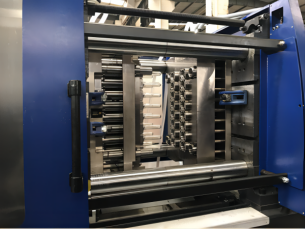
Tie bar distance is a foundational parameter for selecting injection molding machines and designing molds. Engineers must verify compatibility between machine specifications, mold dimensions, and installation methods to ensure efficient production.
Haichen injection machine tie bar
- Manufacturing Process and Quality Control
- Material Strength and Optimization
- Structural Design Parameters
- Application Flexibility
- Safety and Maintenance
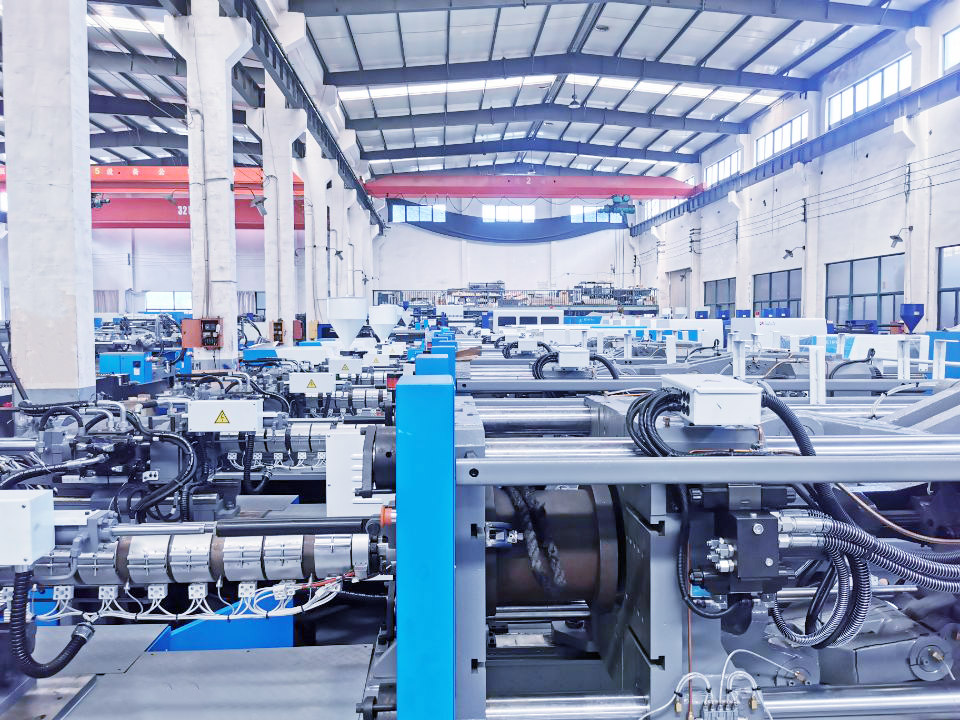
Manufacturing Process and Quality Control
Haichen produces approximately 14,000 tie bars monthly. The production process includes:
- Rough machining
- Initial polishing
- Electroplating (for corrosion resistance)
- Secondary polishing
- Precision thread machining
All tie bars are manufactured in the Third Steel Component Workshop of the Second Factory, overseen by team leader Ye Liwei, who coordinates production schedules to ensure on-time delivery. Each tie bar is rigorously matched to hundreds of machine models, reflecting Haichen’s stringent quality standards.
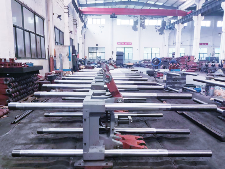
Material Strength and Optimization
- Servo energy-saving machines (e.g., E-Series): Tie bars undergo specialized surface treatments (e.g., hardening or coating) to enhance durability and fatigue resistance.
- Cold-chamber die-casting machines (e.g., HDC-Series): Tie bars feature overstress protection via front platen nuts to prevent uneven force distribution and fractures.
Structural Design Parameters
- Tie Bar Spacing: Varies significantly by machine tonnage.
- Example: A 170-ton injection machine has a spacing of 470×470 mm, while HDC-Series die-casting machines offer larger spacing (e.g., 1350×1350 mm) to accommodate oversized molds.
- Precision Standards:
- Parallelism error of moving/fixed platens under load: ≤0.12 mm.
- Average elongation error across four tie bars: ≤0.1 mm, ensuring uniform force distribution during clamping.
Application Flexibility
Tie bar spacing is optimized for mold compatibility. Haichen’s designs prioritize versatility, such as expanding platen dimensions and refining toggle mechanisms to enable larger molds on same-tonnage machines.
Safety and Maintenance
- Automatic centralized lubrication systems (e.g., E-Series) reduce manual maintenance and extend tie bar lifespan.
- Warranty terms: Damage caused by improper mold installation or unauthorized bolt removal voids the warranty, emphasizing correct operation.
By the end
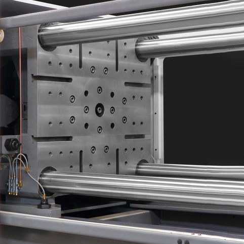
Haichen’s tie bars excel in manufacturing precision, material strength, structural engineering, and maintenance efficiency. Their high accuracy and adaptability to large molds make them ideal for diverse applications, from precision components to heavy-duty industrial products.
Contact Haichen anytime for more information about tie bar in injection molding.